Category Archives: Tech Art

Managing Interactive Game Props

An interactive prop in a game would be any animatable object in the game world that a character interacts with. As an example, to implement a player turning a valve, the player must be positioned at the right place with respect to the valve. Both interaction animations (prop – ‘valve turning’ the player – ‘turning valve’) must be played in sync with each other. What programming needs to implement this:

  •  Some sort of locator node in the prop rig to determine the position of the player with respect to the valve. On pressing the ‘interact’ key somewhere close to the prop, the player will be interpolated to the correct position.
  • The player animation and valve animation, both should be exactly the same in length. These can be played when the player is at the correct position.

The last time we used interactive props, the animators were setting this up manually. The process would involve importing the prop rig (exposing potential naming conflicts) and manually placing the tag in the prop rig at the correct position. Once the prop and character have been animated, they would need to saved out into separate files. This is a very time consuming and error prone process. The ‘Interactive Prop Manager’ tool was created to automate all this for animators. On the surface, the tool allows the animators to import a a prop into an animation file and work on the character and prop in the same scene in Max. In our example, the valve rig can be imported into the player rig scene and the animator can animate the interaction.

propMgr

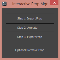
Step 1: Import prop – opens a file browser window to select a file. On import, the prop is placed in the scene using the character reference tag present in the prop file. This step also renames all the nodes in the prop file with a prefix to separate it from the character rig nodes for easy identification.

Step 2: Animate – Animator animates the character and rig.

Step 3: Export Prop – saves out the prop file as its own separate animation. The thing to consider here is that in the prop file, the prop is at the center of the scene, while in the character file, the prop would be offset due to the interaction. This offset is calculated using a non keyable prop root control curve. The prop root control curve will always stay in the center of the prop rig and can be used by the animator to place the prop within the the character rig file. The offset between the player reference tag and the prop root control curve will be the amount the prop scene would need to be moved in the prop rig after export. This offset will also move the player reference tag to the correct position.
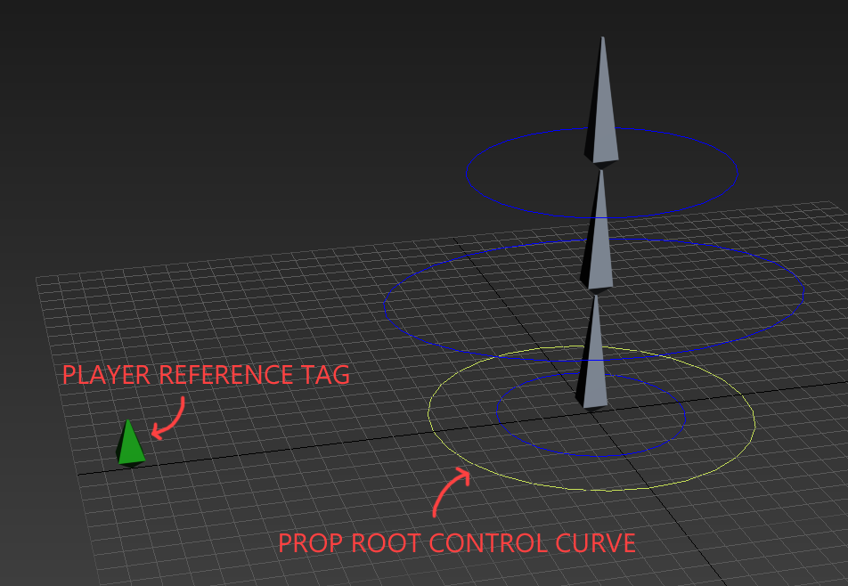
prop_rig

the prop rig file

player_rig

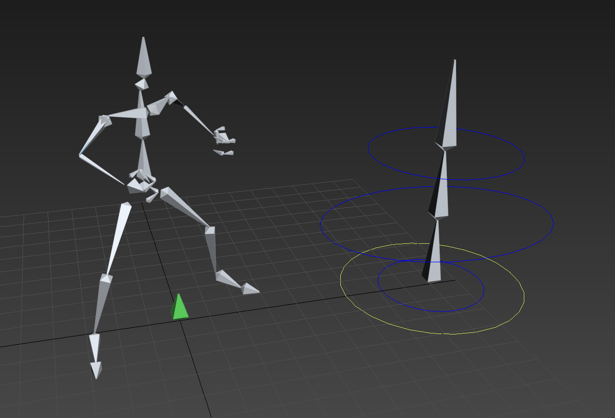
the player rig file, with the prop imported and offset based on ‘player reference tag’

Smooth IK setup


smoothingAlgs

IK smoothing is used to soften the motion of the IK handle as the chain approaches full stretch. It can be set up in the 3ds Max by position constraining the IK handle to two targets with distributed weights. One target should be the IK control curve(CC in gif) and the other, an object placed at the position of the first bone in the IK(FB in gif) chain. The position weights need to be set as script controllers. Given the nodes CC and FB, we can calculate smoothing using the following script for the influence of CC –

Exponential Smoothing:
            x = (distance CC FB) – Rmin
            y = x
            if x > 0 do
            (
                        y = (D – Rmin)*(1-exp(-x/(D – Rmin)))
            )
            r = (Rmin + y)/(Rmin + x)

Trigonometric Smoothing:
            x = (distance CC FB) – Rmin
            L = Rmax – Rmin
            y = x
            if x > 0 and x < L do
            (
                        y = (D – Rmin)*sin(90*x/L)
            )
            r = (Rmin + y)/(Rmin + x)

Rmin is the minimum radius of influence beyond which smoothing starts to take action. Rmax, used only for the trigonometric method and it defines the maximum distance CC needs to be from FB for the arm to be completely stretched out. These values are shown in the figure as the blue curved lines (which are actually circles with the center at FB)

The weight influence of FB can be set as 1 – Influence of CC.

I personally prefer the trigonometric method because it contains the extra Rmin attribute, giving the user more control. Also, it has a more natural motion as CC approaches Rmax.

Reverse FK rig

This rig was skinned to a snake like creature which needed to perform actions like slithering, rearing its head and whipping its tail to attack. A regular spline solution that is commonly used for these kinds of movement was just not cutting it, the involved animator insisted that a much higher quality of animation could be achieved via FK follow through technique. The problem? To animate follow through in a slithering animation, the FK hierarchy should go from the head(parent) to the tail(last child) while, for a rearing animation, the FK hierarchy would need to go in a reverse direction – the rig would need to have FK controls working in both directions. Here is a demo of my solution, the Reverse FK rig:


The only drawback that this rig faced was that the ‘Mid Point’ can’t be keyed in the middle of the animation. It breaks the existing animation of the control curves since the snapping option affects transforms their previously inactive parent objects. This was easily overcome by breaking apart the animation into separate files at the frame when the Mid Point changes. These animations were later stitched together in code.

Dissolve shader

This Shader uses the alpha value of the applied texture to clip parts of the mesh that fall below a specified ‘dissolve amount’ property. The outline of the mesh can be given a custom color and thickness. An artist can manually paint the alpha channel of the texture to achieve a desired dissolve pattern as darker pixels dissolve earlier than lighter pixels.

Object Sway Shader

This Shader uses the R, G and B components of the vertex color on a mesh to sway corresponding vertices via three sets of user defined direction, amplitude and frequency values – one for each component. The RGB values also linearly affects the frequency of sway. Using RGB values allows the artist to paint complex patterns for the mesh to sway. This can be used to create dynamic objects like foliage, flags, curtains etc.