This is a demo of the rig I built for Erica from Til Morning’s Light, developed at Wayforward Technologies.
All animation credit goes to Chris Kerlegon at Wayforward Technologies
Music Source
This is a demo of the rig I built for Erica from Til Morning’s Light, developed at Wayforward Technologies.
All animation credit goes to Chris Kerlegon at Wayforward Technologies
Music Source
Here’s a brief description of a simple setup I created for deployment and update of tools over SVN at my workplace. Prior to this, tools were inefficiently being shared as separate files on a case by case basis. I knew the setup would need to be quick and straightforward from the designers/artists’ perspective. I did not want the end user to spend a lot of time or effort with the tools installation/updates. Also, the most recent version of the tools needed to be accessible by all users across the network.
Tools Folder – The main task was creating an organized and scalable tools folder that contains all the maxscript files. The folder also contains an icon folder, which holds all the custom icons that were created for the tools. A generalHelperFuntions.ms was created in the folder, to contain scripts for the more commonly used functions shared across several tools. Finally, there was the macros.ms file, which contains macroscripts for every script added into the tools folder.
3ds Max setup – 3ds max can be asked to run scripts on startup from a particular folder. The Tools Folder was linked to 3ds max so that whenever 3ds max starts, all the functions contained in the scripts would be initialized (In hindsight, this could be further optimized by separating the base scripts to a different location, and only the macros would be run on startup. The macros themselves would contain the location of the base scripts which could be initialized lazily)
SVN – Once the tools folder was setup and tested with 3ds max, it was checked into SVN. Tools are added/updated and checked into SVN as and when needed. For adding a new script, macros.ms also needs an entry for it.
Client Side Setup – To install the tools for an end user, the Tools Folder would need to be checked out from the repo into the users local drive and 3ds Max would be directed to read scripts from that folder on startup. This is only a one time setup (unless 3ds Max forgets the path to the Tools Folder, in which case it will have to be done again) and is a fairly simple one too.
Client Side Update – Every time a tool is updated/added, the user can SVN update the Tools Folder and restart 3ds Max, and they would have the latest version of the tools up and running.
IK smoothing is used to soften the motion of the IK handle as the chain approaches full stretch. It can be set up in the 3ds Max by position constraining the IK handle to two targets with distributed weights. One target should be the IK control curve(CC in gif) and the other, an object placed at the position of the first bone in the IK(FB in gif) chain. The position weights need to be set as script controllers. Given the nodes CC and FB, we can calculate smoothing using the following script for the influence of CC –
Exponential Smoothing:
x = (distance CC FB) – Rmin
y = x
if x > 0 do
(
y = (D – Rmin)*(1-exp(-x/(D – Rmin)))
)
r = (Rmin + y)/(Rmin + x)
Trigonometric Smoothing:
x = (distance CC FB) – Rmin
L = Rmax – Rmin
y = x
if x > 0 and x < L do
(
y = (D – Rmin)*sin(90*x/L)
)
r = (Rmin + y)/(Rmin + x)
Rmin is the minimum radius of influence beyond which smoothing starts to take action. Rmax, used only for the trigonometric method and it defines the maximum distance CC needs to be from FB for the arm to be completely stretched out. These values are shown in the figure as the blue curved lines (which are actually circles with the center at FB)
The weight influence of FB can be set as 1 – Influence of CC.
I personally prefer the trigonometric method because it contains the extra Rmin attribute, giving the user more control. Also, it has a more natural motion as CC approaches Rmax.
This rig was skinned to a snake like creature which needed to perform actions like slithering, rearing its head and whipping its tail to attack. A regular spline solution that is commonly used for these kinds of movement was just not cutting it, the involved animator insisted that a much higher quality of animation could be achieved via FK follow through technique. The problem? To animate follow through in a slithering animation, the FK hierarchy should go from the head(parent) to the tail(last child) while, for a rearing animation, the FK hierarchy would need to go in a reverse direction – the rig would need to have FK controls working in both directions. Here is a demo of my solution, the Reverse FK rig:
The only drawback that this rig faced was that the ‘Mid Point’ can’t be keyed in the middle of the animation. It breaks the existing animation of the control curves since the snapping option affects transforms their previously inactive parent objects. This was easily overcome by breaking apart the animation into separate files at the frame when the Mid Point changes. These animations were later stitched together in code.
This might be blatantly obvious for experienced game TAs but since I had a hard time figuring this out when I started, I’ll leave this right here…
In most current engines, for a given animated entity, an animation is ‘played’ on a base rig. The base rig is the rigged mesh file with no animation data. In the engine, the animations are applied onto the base rig and what you see in game, will be an instance of this base rig. This base rig should ideally contain only the most essential objects required for it to run in game. These are just the bones and the skinned mesh. On the other hand, a rig that is handed over to animators would contain several control curves and dummy objects with complex relations to each other which drive the bone hierarchy through constraints( and not through parenting ). It is important to keep the hierarchy of these drivers completely separate from the bone hierarchy to observe somewhat of an ‘abstraction’.
So ideally, this is how the hierarchy in your rig should look like (3Ds Max schematic view for a simple Turret rig). When the rig is exported to engine, it should be stripped of all control curves (an animator level abstraction)
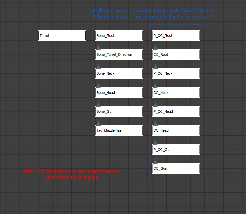
This kind of abstraction provides various advantages: