Author Archives: arvindk.86@gmail.com

Reverse FK rig

This rig was skinned to a snake like creature which needed to perform actions like slithering, rearing its head and whipping its tail to attack. A regular spline solution that is commonly used for these kinds of movement was just not cutting it, the involved animator insisted that a much higher quality of animation could be achieved via FK follow through technique. The problem? To animate follow through in a slithering animation, the FK hierarchy should go from the head(parent) to the tail(last child) while, for a rearing animation, the FK hierarchy would need to go in a reverse direction – the rig would need to have FK controls working in both directions. Here is a demo of my solution, the Reverse FK rig:


The only drawback that this rig faced was that the ‘Mid Point’ can’t be keyed in the middle of the animation. It breaks the existing animation of the control curves since the snapping option affects transforms their previously inactive parent objects. This was easily overcome by breaking apart the animation into separate files at the frame when the Mid Point changes. These animations were later stitched together in code.
Dissolve shader

This Shader uses the alpha value of the applied texture to clip parts of the mesh that fall below a specified ‘dissolve amount’ property. The outline of the mesh can be given a custom color and thickness. An artist can manually paint the alpha channel of the texture to achieve a desired dissolve pattern as darker pixels dissolve earlier than lighter pixels.

Object Sway Shader

This Shader uses the R, G and B components of the vertex color on a mesh to sway corresponding vertices via three sets of user defined direction, amplitude and frequency values – one for each component. The RGB values also linearly affects the frequency of sway. Using RGB values allows the artist to paint complex patterns for the mesh to sway. This can be used to create dynamic objects like foliage, flags, curtains etc.

Game Rigs: Controls vs Bones Hierarchy Abstraction

This might be blatantly obvious for experienced game TAs but since I had a hard time figuring this out when I started, I’ll leave this right here…

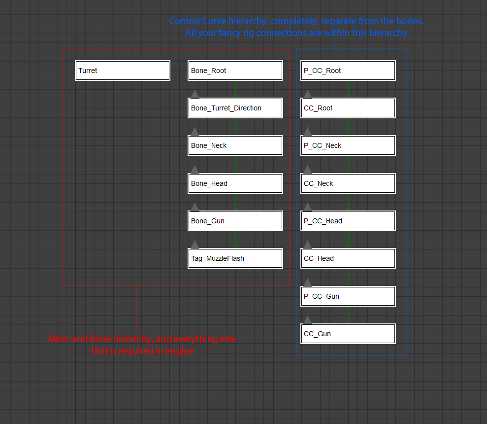
In most current engines, for a given animated entity, an animation is ‘played’ on a base rig. The base rig is the rigged mesh file with no animation data. In the engine, the animations are applied onto the base rig and what you see in game, will be an instance of this base rig. This base rig should ideally contain only the most essential objects required for it to run in game. These are just the bones and the skinned mesh. On the other hand, a rig that is handed over to animators would contain several control curves and dummy objects with complex relations to each other which drive the bone hierarchy through constraints( and not through parenting ). It is important to keep the hierarchy of these drivers completely separate from the bone hierarchy to observe somewhat of an ‘abstraction’.

So ideally, this is how the hierarchy in your rig should look like (3Ds Max schematic view for a simple Turret rig). When the rig is exported to engine, it should be stripped of all control curves (an animator level abstraction)

hierarchy

This kind of abstraction provides various advantages:

  • Simpler hierarchies for game objects, easy parsing at engine side
  • Art can go overboard on the amount of complication of the rig
  • Rig iterations can be performed at two separate levels depending on the need. The engine might demand a different bone hierarchy than the animator

Forearm Twist Bone Setup Using Transforms

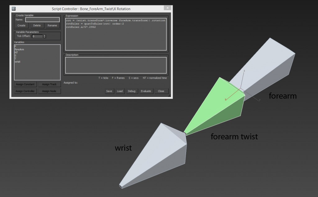
Here’s a setup to create a forearm twist bone ..

The twist bone is parented to the forearm bone and the X rotation of the twist bone is a script controller which has the following formula:

rot = (wrist.transform*(inverse foreArm.transform)).rotation
rotEuler = quatToEuler(rot) order:2
rotEuler.x/57.2952

Here, foreArm is the forearm bone node and wrist is the wrist bone node. The formula basically gets the transform of the the wrist bone with respect to the forearm bone and extracts the x rotation (local X axis points along the bone and z points up for all three bones). This is cleaner than a Look At constraint method and also does not use the controller of the wrist/forearm bones directly (which usually have a weighted orient constraint for FK/IK switching). This method does cause flipping when the wrist rotated more than 90 degrees sideways – an unlikely situation for wrists ( If you are getting the flipping on up and down rotation, try changing the rotation order in the the quatToEuler method )

If there are multiple twist bones, they can be orient constrained to the first twist bone and the forearm bone, with gradually decreasing weights of the twist bone’s influence as you move up closer to the elbow.